Table of Contents
Introduction
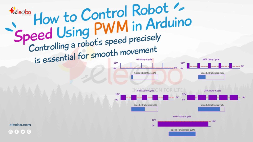
If you want to control robot speed using PWM in Arduino, you are in the right place. Controlling a robot’s speed precisely is essential for smooth movement, better efficiency, and enhanced performance. The best way to achieve this is by using Pulse Width Modulation (PWM) in Arduino.
In this guide, you will learn everything about how to control robot speed using PWM in Arduino, why PWM is the best method, and how to implement it with a practical example. By the end of this guide, you will be able to fine-tune your robot’s speed with ease.
What is PWM and Why Use It for Controlling Robot Speed?
PWM (Pulse Width Modulation) is a technique that controls power delivery to motors by switching them on and off rapidly. The average voltage sent to the motor determines the speed. The duty cycle (percentage of the ON time) controls how fast or slow the motor moves.
When you control robot speed using PWM in Arduino, you can achieve smooth acceleration, precise control, and efficient power usage. PWM allows you to vary the speed of a DC motor by adjusting the duty cycle without losing torque.
Duty cycle
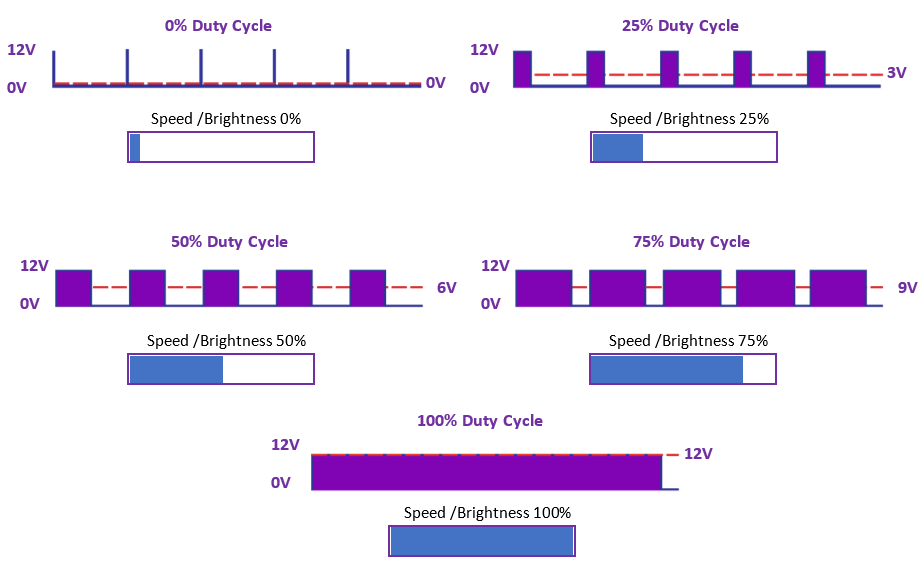
The duty cycle refers to the proportion of time that a signal is in the “on” state compared to the total time of a complete cycle. In the context of PWM (Pulse Width Modulation), the duty cycle represents the percentage of time the signal is “on” versus the total time of one cycle.
For example, if a signal is on for 75% of the time and off for 25% of the time during one cycle, then the duty cycle is 75%. This duty cycle determines the average power or voltage delivered to a device, such as a motor or a light, in PWM applications. A higher duty cycle means more time spent in the “on” state, resulting in higher average power, while a lower duty cycle means less time in the “on” state and lower average power.
In PWM (Pulse Width Modulation), the range 0 to 255 corresponds to an 8-bit digital signal where:
- 0 = 0% duty cycle (always OFF)
- 255 = 100% duty cycle (always ON)
So, common values map like this:
- 0 = 0% duty cycle
- 64 = 25% duty cycle
- 127 = 50% duty cycle
- 191 = 75% duty cycle
- 255 = 100% duty cycle
In Arduino, this is commonly used with the analogWrite() function. For example:
analogWrite(motorPin, 127);  // 50% speed
analogWrite(motorPin, 64);   // 25% speed
analogWrite(motorPin, 255);  // 100% speed
The reason for using 0-255 specifically is because 8 bits can represent 256 different values (2^8 = 256), giving you fine control over the duty cycle. This allows for precise speed control in motors or brightness control in LEDs.
PWM ranges for different Arduino boards:
For 8-bit Arduino boards (UNO, Nano, Mini, Mega):
analogWrite(pin, 0-255)    // 8-bit PWM resolution
// Examples:
analogWrite(pin, 0);       // 0% duty cycle
analogWrite(pin, 255);     // 100% duty cycle
For 10-bit capable boards (Due):
analogWrite(pin, 0-1023)   // 10-bit PWM resolution
// Examples:
analogWrite(pin, 0);       // 0% duty cycle
analogWrite(pin, 1023);    // 100% duty cycle
For 12-bit capable boards (Zero, MKR family):
analogWrite(pin, 0-4095)   // 12-bit PWM resolution
// Examples:
analogWrite(pin, 0);       // 0% duty cycle
analogWrite(pin, 4095);    // 100% duty cycle
The resolution depends on the microcontroller:
- 8-bit (0-255): UNO, Nano, Mini, Mega
- 10-bit (0-1023): Due
- 12-bit (0-4095): Zero, MKR boards
- Some boards like ESP32 can even be configured for different PWM resolutions
When using any board, make sure to check its specific PWM resolution in the documentation to use the full range correctly.
Components Required
To control robot speed using PWM in Arduino, you will need:
- Arduino Board (Uno, Mega, or Nano)
- L298N Motor Driver Module
- DC Motor
- Battery (9V or 12V)
- Jumper Wires
Now that we have the required components, let’s dive into the wiring and coding part.
Wiring Diagram
Before writing the code, let’s set up the connections correctly:
- Connect the Motor Driver to Arduino:
- Connect IN1 and IN2 of the L298N module to Arduino Pins 9 and 10.
- Connect Enable A (ENA) to Arduino Pin 5 (PWM Pin).
- Connect the Ground (GND) of the motor driver to the GND of Arduino.
- Connect the DC Motor to the Motor Driver:
- Attach the motor’s two terminals to the OUT1 and OUT2 of the L298N driver.
- Power the Circuit:
- Connect the VCC of the motor driver to the Battery’s Positive Terminal.
- Connect the Battery’s Negative Terminal to the GND of Arduino and Motor Driver.
Your wiring is now complete, and you are ready to write the code!
Arduino Code for Controlling Robot Speed Using PWM
#define ENA 5  // PWM pin for speed control
#define IN1 9  // Motor direction control
#define IN2 10 // Motor direction control

void setup() {
    pinMode(ENA, OUTPUT);
    pinMode(IN1, OUTPUT);
    pinMode(IN2, OUTPUT);
}

void loop() {
    digitalWrite(IN1, HIGH);
    digitalWrite(IN2, LOW);

    for (int speed = 0; speed <= 255; speed += 5) {
        analogWrite(ENA, speed);
        delay(100);
    }

    delay(1000);

    for (int speed = 255; speed >= 0; speed -= 5) {
        analogWrite(ENA, speed);
        delay(100);
    }
}
This code gradually increases the motor speed from 0% to 100% and then reduces it back to 0% using PWM.
Explanation of the Code
- The ENA pin controls the speed of the motor using analogWrite().
- The IN1 and IN2 pins determine the motor’s direction.
- The for loop smoothly increases and decreases speed, demonstrating how to control robot speed using PWM in Arduino effectively.
Why PWM is Ideal for Robot Speed Control
When you control robot speed using PWM in Arduino, you benefit from:
- Energy Efficiency – Only the required power is delivered.
- Smooth Acceleration and Deceleration – Prevents jerky motion.
- Precise Speed Control – Adjust speed with high accuracy.
- Minimal Heat Generation – Reduces power loss.
Using PWM in Arduino is the best way to ensure your robot moves at a controlled and efficient speed.
Optimizing PWM for Smooth Robot Motion
Here are some tips to optimize your PWM speed control:
- Use a Soft-Start Mechanism – Gradually increase speed instead of sudden jumps.
- Calibrate PWM Values – Experiment with different duty cycles to find the best settings.
- Implement Sensors – Use sensors to adjust speed dynamically based on obstacles or terrain.
- Use Interrupts for Better Control – Instead of using delays, use interrupts for real-time speed adjustments.
By following these tips, you can control robot speed using PWM in Arduino with better precision and efficiency.
Common Issues and Troubleshooting
1. Motor Not Spinning?
- Check if the L298N module is receiving power.
- Ensure the motor connections are correct.
2. Motor Running at Constant Speed?
- Verify that you are using the PWM pin for speed control.
- Check if the duty cycle values are changing in the code.
3. Motor Overheating?
- Use a heat sink on the motor driver.
- Reduce the duty cycle if full speed is not necessary.
These troubleshooting tips will help you fix common problems and improve the performance of your robot.
Conclusion
Now, you know how to control robot speed using PWM in Arduino efficiently. By using PWM signals, you can smoothly adjust your robot’s speed, optimize power usage, and enhance overall performance.
Start experimenting today! Modify the code, test different PWM values, and see how your robot responds. Controlling robot speed using PWM in Arduino is a fundamental skill that will take your robotics projects to the next level.
If you found this guide helpful, share it with other robotics enthusiasts and keep innovating!
Download BlueBot Controller App and start your journey today!