The SPI protocol is one of the most widely used communication protocols in embedded systems and microcontrollers. Whether you’re working with Arduino, designing IoT devices, or developing complex embedded systems, understanding the SPI protocol is essential. In this blog, we’ll dive deep into what the SPI protocol is, how it works, and its applications in various systems. By the end, you’ll have a solid grasp of SPI communication and how to implement it effectively.
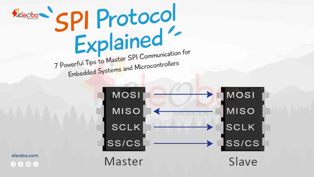
Table of Contents
What is SPI Protocol?
The SPI protocol, or Serial Peripheral Interface, is a synchronous serial communication protocol used for short-distance communication. It enables high-speed data exchange between microcontrollers, sensors, memory devices, and other peripherals. The SPI interface is known for its simplicity, efficiency, and versatility, making it a popular choice in embedded systems.
Unlike other communication protocols like I2C or UART, the SPI protocol uses a master-slave architecture. This means one device (the master) controls the communication, while one or more devices (the slaves) respond to the master’s commands.
How Does SPI Communication Work?
The SPI communication protocol relies on four main signals:
- SCLK (Serial Clock): Generated by the master, this signal synchronizes data transmission.
- MOSI (Master Out Slave In): The master sends data to the slave through this line.
- MISO (Master In Slave Out): The slave sends data back to the master through this line.
- SS/CS (Slave Select/Chip Select): The master uses this line to select which slave to communicate with.
Here’s how the SPI protocol works in action:
- The master initiates communication by pulling the SS/CS line low for the target slave.
- The master generates a clock signal (SCLK) to synchronize data transfer.
- Data is sent bit by bit through the MOSI and MISO lines.
- Once the data transfer is complete, the master pulls the SS/CS line high to end communication.
SPI Modes
SPI has 4 modes, depending on two settings:
- CPOL (Clock Polarity): Determines if the clock is high or low when idle.
- CPHA (Clock Phase): Determines when data is sampled (read) and shifted (sent).
| SPI Mode | CPOL | CPHA | Description |
|---|---|---|---|
| 0 | 0 | 0 | Clock idle = low. Data sampled on rising edge, shifted on falling edge. |
| 1 | 0 | 1 | Clock idle = low. Data sampled on falling edge, shifted on rising edge. |
| 2 | 1 | 0 | Clock idle = high. Data sampled on falling edge, shifted on rising edge. |
| 3 | 1 | 1 | Clock idle = high. Data sampled on rising edge, shifted on falling edge. |
SPI in Embedded Systems
In embedded systems, the SPI protocol is a game-changer. Its high-speed data transfer and simplicity make it ideal for applications like:
- Sensor interfacing: Connecting temperature, pressure, or motion sensors.
- Memory devices: Communicating with flash memory or EEPROM.
- Display modules: Driving LCD or OLED displays.
- Wireless communication: Interfacing with Wi-Fi or Bluetooth modules.
For example, in a smart home system, an embedded microcontroller might use the SPI interface to communicate with a temperature sensor and a Wi-Fi module simultaneously.
SPI in Arduino
Arduino boards are widely used for prototyping, and the SPI protocol plays a crucial role in expanding their capabilities. Most Arduino boards, like the Arduino Uno, have dedicated pins for SPI communication:
- MOSI (Pin 11)
- MISO (Pin 12)
- SCLK (Pin 13)
- SS (Pin 10)
Here’s an example of using the SPI protocol in Arduino to communicate with an SPI-based sensor:
#include <SPI.h>

void setup() {
  SPI.begin(); // Initialize SPI communication
  pinMode(SS, OUTPUT); // Set SS pin as output
  digitalWrite(SS, HIGH); // Keep SS high initially
}

void loop() {
  digitalWrite(SS, LOW); // Select the slave
  SPI.transfer(0x55); // Send data to the slave
  digitalWrite(SS, HIGH); // Deselect the slave
  delay(1000); // Wait for 1 second
}
This simple example demonstrates how the SPI protocol can be used to send data from an Arduino to an SPI device.
Serial Peripheral Interface (SPI) Protocol Configurations
The SPI protocol is a widely used communication standard that enables efficient data exchange between microcontrollers and peripheral devices. By adjusting various settings and parameters, developers can tailor the SPI protocol to meet the specific requirements of their applications. Below are the key configurations for the SPI protocol:
- Clock Polarity (CPOL)
The SPI protocol allows you to set the idle state of the clock signal. It can be configured as either idle high (CPOL=1) or idle low (CPOL=0). For seamless communication, all devices must agree on the clock polarity. - Clock Phase (CPHA)
In the SPI protocol, CPHA determines when data is sampled and shifted during each clock cycle. It can be set to capture data on the leading edge (CPHA=0) or the trailing edge (CPHA=1) of the clock signal. - Bit Order
The SPI protocol supports configuring the bit order, specifying whether the most significant bit (MSB) or the least significant bit (LSB) is transmitted first. Devices must align on the bit order to ensure accurate data interpretation. - Clock Speed (Clock Frequency)
The clock speed in the SPI protocol determines the rate at which clock pulses are generated during communication. It is typically measured in hertz (Hz) and can be adjusted to meet the timing requirements of connected devices. - Data Frame Format
The SPI protocol allows you to define the size and structure of each data frame. This includes parameters such as the number of bits per frame, data format (e.g., standard or extended), and any additional control bits. - Chip Select (CS) Configuration
In the SPI protocol, chip-select pins are used to select individual slave devices for communication. The configuration specifies how these pins are activated and deactivated during SPI transactions. - Full-Duplex or Half-Duplex Mode
The SPI protocol supports both full-duplex and half-duplex communication modes. In full-duplex mode, data can be transmitted and received simultaneously, while in half-duplex mode, devices alternate between transmitting and receiving data. - Error Handling and Clock Synchronization
The SPI protocol may include mechanisms for error detection and clock synchronization to ensure reliable communication, especially in noisy environments or over long distances.
By fine-tuning these configurations, developers can optimize the SPI protocol for factors such as speed, timing, and compatibility with connected devices. Properly understanding and configuring the SPI protocol is essential for successfully integrating SPI-enabled components in embedded systems and IoT devices.
Serial Peripheral Interface (SPI) Protocol Types
The SPI protocol comes in various types, each offering unique features and capabilities. These variations provide flexibility in communication between microcontrollers and peripheral devices. Below are the different types of the SPI protocol:
- Standard SPI
This is the most widely used type of the SPI , featuring a single master device communicating with one or more slave devices using separate chip-select lines. It operates in full-duplex mode, enabling simultaneous data transmission and reception. - Single SPI (SSI)
Single SPI, or SSI, involves a single master device communicating with a single slave device. Unlike standard SPI, SSI uses a shared chip-select line for all connected slave devices. This simplifies hardware configuration but limits communication to one slave at a time. - Multi-Master SPI
In Multi-Master SPI, multiple master devices share communication with one or more slave devices. Each master can initiate communication independently, enabling more complex network configurations. However, proper coordination is required to prevent data collisions. - Daisy Chain SPI
Daisy Chain SPI connects multiple slave devices in a chain configuration, with data passing through each slave sequentially. This reduces the number of chip-select lines needed, making it suitable for applications with limited pins. However, it may introduce delays as data propagates through the chain. - Quad SPI (QSPI)
Quad SPI enhances the SPI by increasing data transfer rates using four data lines (MOSI, MISO, and two clock lines). This parallel data transfer enables faster communication, making it ideal for high-speed applications such as flash memory and displays. - Serial Peripheral Interface Bus (SPI Bus)
SPI Bus is a variation of the SPI protocol that uses a shared data bus, allowing multiple master and slave devices to communicate over the same set of data lines. It employs additional control signals for arbitration and synchronization, ensuring orderly communication in multi-device environments. - Enhanced Serial Peripheral Interface (eSPI)
eSPI is an advanced version of the SPIdesigned for modern computing systems. It offers features like increased data rates, extended address space, and additional functionalities such as system management and security. It is commonly used in embedded systems, servers, and networking equipment.
Each type of the SPI protocol offers distinct advantages and is suited for different applications based on factors such as speed, simplicity, and system requirements. Understanding these variations allows developers to choose the most appropriate SPI protocol configuration for their specific project needs, ensuring efficient and reliable communication between devices.
Why the SPI is Essential for Modern Electronics
The SPI protocol is a cornerstone of modern electronics, enabling seamless communication between microcontrollers and peripheral devices. Its flexibility, speed, and simplicity make it a popular choice for a wide range of applications, from IoT devices to industrial automation. By mastering the configurations and types of the SPI protocol, developers can unlock its full potential and create robust, high-performance systems. Whether you’re working on a simple embedded project or a complex multi-device network, the SPI protocol provides the tools you need to achieve reliable and efficient communication.
SPI in Microcontrollers
Microcontrollers like the ATmega328P (used in Arduino) and STM32 series have built-in SPI interfaces. These interfaces simplify the implementation of the SPI protocol in your projects.
For instance, the STM32 microcontroller can act as both an SPI master and slave. This flexibility allows it to communicate with multiple SPI devices, making it a powerful choice for complex embedded systems.
Advantages of SPI Protocol
- High Speed: The SPI protocol supports faster data transfer rates compared to I2C or UART.
- Full-Duplex Communication: Data can be sent and received simultaneously.
- Simplicity: The SPI interface is easy to implement and requires minimal hardware.
- Flexibility: It supports multiple slaves, making it suitable for complex systems.
Challenges of SPI Protocol
While the SPI protocol is powerful, it has some limitations:
- Limited Distance: It’s not suitable for long-distance communication.
- No Error Detection: Unlike I2C, the SPI protocol lacks built-in error detection.
- Increased Pin Count: Each slave requires a separate SS/CS line, which can increase pin usage.
Practical Example: SPI in Action
Let’s consider a real-world example of the SPI protocol in an embedded system. Imagine you’re designing a weather station that collects data from multiple sensors and displays it on an LCD.
- Temperature Sensor: The microcontroller uses the SPI interface to read temperature data from an SPI-based sensor.
- Humidity Sensor: Another SPI-based sensor provides humidity data.
- LCD Display: The microcontroller sends the collected data to an SPI-driven LCD for display.
In this setup, the SPI protocol ensures fast and reliable communication between all components.
History of SPI
The SPI protocol was developed by Motorola in the 1980s. Over the years, it has become a de facto standard for short-distance communication in embedded systems and microcontrollers. Its simplicity, speed, and versatility have made it a popular choice for engineers and developers worldwide.
Conclusion
The SPI protocol is a cornerstone of modern embedded systems and microcontrollers. Its speed, simplicity, and versatility make it an indispensable tool for engineers and hobbyists alike. Whether you’re working with Arduino, designing IoT devices, or developing complex systems, mastering the SPI protocol will unlock new possibilities for your projects.
By understanding how the SPI communication protocol works and applying it in real-world scenarios, you can take your embedded systems to the next level. So, dive into the world of SPI interface and start building innovative solutions today!
For Bluetooth Project : Download BlueBot Controller App and start your journey today!