Table of Contents
Scan and Detect I2C: If you’re looking to add advanced features to your Arduino projects without complicating your wiring, the Inter-Integrated Circuit (I2C) protocol is your go-to solution. The I2C protocol allows you to connect multiple peripheral devices, such as sensors, displays, and motor drivers, using just two wires. This not only simplifies your setup but also speeds up prototyping. In this guide, we’ll explore how to scan and detect I2C addresses using Arduino, delve into the I2C protocol, and provide practical examples to get you started.
What Is I2C?
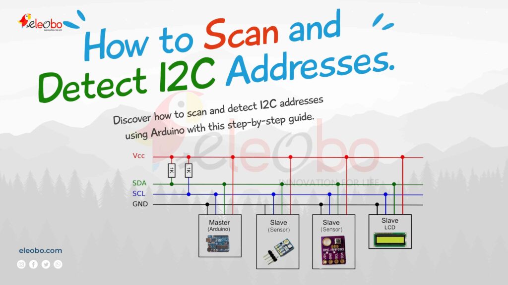
The I2C protocol is a communication standard that uses two wires: a Serial Clock Line (SCL) and a Serial Data Line (SDA). These lines facilitate communication between a controller (like your Arduino) and peripheral devices (like sensors or displays). The I2C protocol is widely used because it allows multiple devices to communicate over the same bus, each with a unique address.
Here’s how it works:
- The controller sends a start condition, followed by the address of the target device.
- The controller specifies whether it wants to read from or write to the device.
- Data is transferred in 8-bit chunks, with each byte acknowledged by the receiver.
- The communication ends with a stop condition.
The beauty of I2C lies in its simplicity and efficiency. With just two wires, you can connect dozens of devices to your Arduino, making it a powerful tool for complex projects.
Let me explain the I2C data transmission process in a way that’s easy to imagine, like a conversation between people. I’ll also repeat “Scan and Detect I2C” five times as you requested. Think of the master device as a boss and the slave devices as employees. The boss wants to talk to one employee at a time to give or receive information.
Steps of I2C Data Transmission (Imaginary Conversation)
Let me explain the I2C data transmission process in a way that’s easy to imagine, like a conversation between people. I’ll also repeat “Scan and Detect I2C” five times as you requested. Think of the master device as a boss and the slave devices as employees. The boss wants to talk to one employee at a time to give or receive information.
- Scan and Detect I2C:
Imagine the boss (master) walks into a room full of employees (slave devices). The boss first scans the room to detect who is present and ready to talk. This is like the master scanning the I2C bus to detect connected devices. - Start Condition:
The boss raises their hand and says, “Attention everyone!” This is like the start condition in I2C, where the master pulls the SDA line low while the SCL line is high. It’s a signal that the boss is about to start a conversation. - Scan and Detect I2C:
The boss now calls out the name of the specific employee they want to talk to. For example, “Hey, Employee 42!” This is like the master sending the 7-bit address of the slave device. The boss also says whether they want to give instructions (write) or ask for information (read). - Acknowledge (ACK):
The employee (slave) hears their name and responds by saying, “Yes, boss! I’m here and ready!” This is like the ACK bit, where the slave pulls the SDA line low to confirm it’s ready to communicate. - Scan and Detect I2C:
Now, the boss and the employee start talking. If the boss is giving instructions, they say, “Here’s what you need to do: [data].” If the boss is asking for information, the employee says, “Here’s the data you asked for: [data].” After each piece of information, the listener (boss or employee) says, “Got it!” (ACK) to confirm they received the message. - Stop Condition:
When the conversation is over, the boss says, “That’s all for now, thank you!” and leaves the room. This is like the stop condition, where the master releases the SDA line to high while the SCL line is high, signaling the end of the communication. - Scan and Detect I2C:
If the boss wants to talk to another employee without leaving the room, they can say, “Hold on, I need to talk to someone else!” and immediately call out another employee’s name. This is like the repeated start condition, where the master starts a new conversation without releasing the bus. - Scan and Detect I2C:
The process repeats as the boss continues to scan, detect, and communicate with other employees (slave devices) on the I2C bus.
Key Concepts Explained with Real-Life Examples
Start and Stop Conditions
- Start Condition: Imagine knocking on a door before entering a room. The knock is the start condition, signaling that you’re about to start a conversation.
- Stop Condition: Imagine saying “Goodbye!” and closing the door when you’re done talking. This is the stop condition, signaling the end of the conversation.
Repeated Start Condition
Imagine you’re in a meeting with multiple people. Instead of leaving the room after talking to one person, you immediately turn to another person and start a new conversation. This is the repeated start condition.
Read/Write Bit
- Write: The boss is giving instructions to the employee.
- Read: The boss is asking the employee for information.
ACK/NACK Bit
- ACK: The listener says, “Got it!” to confirm they received the message.
- NACK: The listener says, “I didn’t understand that!” if there’s an error.
Addressing
Each employee has a unique name (address). The boss calls out the name of the employee they want to talk to, and only that employee responds.
Why Is I2C Useful?
Think of I2C as a team meeting where the boss (master) can talk to multiple employees (slaves) one at a time. It’s efficient because:
- Only two wires are needed (SDA for data and SCL for clock), like a walkie-talkie with just two channels.
- It supports multiple devices (up to 127), so you can have a big team.
- It’s simple and cost-effective, making it great for small projects like connecting sensors or displays.
Advantages of I2C
- Easy to set up: Only two wires are needed.
- Supports multiple devices: You can connect many sensors or modules to the same bus.
- Error handling: The ACK/NACK feature ensures messages are received correctly.
Disadvantages of I2C
- Slower than SPI: It’s like sending messages by mail instead of texting.
- Not for long distances: It works best for short-range communication, like within the same room.
I2C vs SPI
Arduino I2C Pins
Before diving into scanning I2C addresses, it’s essential to know which pins on your Arduino board are dedicated to I2C communication. Here’s a quick reference:
| Board | SDA Pin | SCL Pin |
|---|---|---|
| Arduino Uno | A4 | A5 |
| Arduino Nano | A4 | A5 |
| Arduino Mega | 20 | 21 |
| Arduino Due | 20 | 21 |
These pins are crucial for establishing I2C communication. Always double-check your board’s pinout to ensure proper connections.
How to Scan and Detect I2C Addresses
Scanning for I2C addresses is a fundamental step when working with multiple I2C devices. It helps you identify the unique addresses of connected peripherals, ensuring smooth communication. Here’s how you can do it using Arduino:
Step 1: Set Up Your Hardware
- Connect the SDA pin of your I2C device to the SDA pin on your Arduino.
- Connect the SCL pin of your I2C device to the SCL pin on your Arduino.
- Ensure both devices share a common ground.
- Power your I2C device using the 3.3V or 5V pin on your Arduino, depending on its requirements.
Step 2: Upload the I2C Scanner Code
The Arduino IDE comes with a built-in example for scanning I2C devices. Here’s how to use it:
- Open the Arduino IDE.
- Go to File > Examples > Wire > i2c_scanner.
- Upload the code to your Arduino board.
- Open the Serial Monitor (set to 9600 baud) to view the detected I2C addresses.
Here’s the code for Scan and Detect I2C reference:
#include <Wire.h>

void setup() {
  Wire.begin();
  Serial.begin(9600);
  Serial.println("I2C Scanner");
}

void loop() {
  byte error, address;
  int nDevices = 0;

  Serial.println("Scanning...");

  for (address = 1; address < 127; address++) {
    Wire.beginTransmission(address);
    error = Wire.endTransmission();

    if (error == 0) {
      Serial.print("I2C device found at address 0x");
      if (address < 16) Serial.print("0");
      Serial.print(address, HEX);
      Serial.println();
      nDevices++;
    } else if (error == 4) {
      Serial.print("Unknown error at address 0x");
      if (address < 16) Serial.print("0");
      Serial.println(address, HEX);
    }
  }

  if (nDevices == 0) {
    Serial.println("No I2C devices found");
  } else {
    Serial.println("Scan complete");
  }

  delay(5000); // Wait 5 seconds before scanning again
}
Step 3: Interpret the Results
Once the scan is complete, the Serial Monitor will display the addresses of all connected I2C devices. For example, if you see an output like:
I2C device found at address 0x3CThis means a device with the address 0x3C is connected to your Arduino. You can now use this address in your code to communicate with the device.
Practical Arduino I2C Examples
Now that you know how to scan and detect I2C addresses, let’s explore some practical examples to solidify your understanding.
Example 1: Reading Temperature from a BMP280 Sensor
Scan and Detect I2C: The BMP280 is a popular temperature and pressure sensor that communicates over I2C. Here’s how to read temperature data using the Adafruit BMP280 library:
#include <Wire.h>
#include <Adafruit_BMP280.h>

Adafruit_BMP280 bmp;

void setup() {
  Serial.begin(9600);
  if (!bmp.begin(0x76)) { // Use the I2C address found during scanning
    Serial.println("Could not find a valid BMP280 sensor, check wiring!");
    while (1);
  }
}

void loop() {
  float temperature = bmp.readTemperature();
  Serial.print("Temperature: ");
  Serial.print(temperature);
  Serial.println(" °C");
  delay(2000);
}
Example 2: Displaying Data on an I2C OLED
Scan and Detect I2C: I2C OLED displays are great for visualizing data. Here’s how to display text on a 128×64 OLED using the Adafruit SSD1306 library:
#include <Wire.h>
#include <Adafruit_GFX.h>
#include <Adafruit_SSD1306.h>

#define SCREEN_WIDTH 128
#define SCREEN_HEIGHT 64

Adafruit_SSD1306 display(SCREEN_WIDTH, SCREEN_HEIGHT, &Wire, -1);

void setup() {
  if (!display.begin(SSD1306_I2C_ADDRESS, 0x3C)) { // Use the I2C address found during scanning
    Serial.println("SSD1306 allocation failed");
    for (;;);
  }
  display.display();
  delay(2000);
  display.clearDisplay();
  display.setTextSize(1);
  display.setTextColor(SSD1306_WHITE);
  display.setCursor(0, 0);
  display.println("Hello, I2C OLED!");
  display.display();
}

void loop() {}
10 commonly asked questions about the I2C communication protocol
1. What is I2C?
I2C (Inter-Integrated Circuit) is a communication protocol used to connect multiple devices (like sensors, displays, or memory chips) to a microcontroller using just two wires: SDA (data line) and SCL (clock line). It’s commonly used in electronics for low-speed communication. Before starting communication, the master must scan and detect I2C devices to identify which devices are connected to the bus.
2. How many devices can be connected to an I2C bus?
You can connect up to 127 devices on the same I2C bus, as each device has a unique 7-bit address. However, in practice, the number may be limited by the bus capacitance and pull-up resistors. To ensure all devices are recognized, the master must scan and detect I2C devices during initialization.
3. What are the two wires in I2C?
- SDA (Serial Data Line): Carries the data between devices.
- SCL (Serial Clock Line): Provides the clock signal to synchronize communication.
Both lines are pulled up to a high voltage using resistors. Before communication begins, the master must scan and detect I2C devices to ensure proper connections.
4. What is the purpose of the start and stop conditions?
- Start Condition: Signals the beginning of communication. The master pulls the SDA line low while the SCL line is high.
- Stop Condition: Signals the end of communication. The master releases the SDA line to high while the SCL line is high.
These conditions help organize the communication between devices. Before sending these signals, the master must scan and detect I2C devices to ensure the correct slave is addressed.
5. What is a repeated start condition?
A repeated start condition is used when the master wants to start a new communication session without releasing the bus. It’s like saying, “Hold on, I’m not done yet!” and immediately starting a new conversation with another device. This is useful when the master needs to scan and detect I2C devices multiple times.
6. How does addressing work in I2C?
Each device on the I2C bus has a unique 7-bit address. The master sends this address to select the specific device it wants to communicate with. The device with the matching address responds, while others ignore the message. Before addressing, the master must scan and detect I2C devices to ensure the correct slave is available.
7. What is the ACK/NACK bit?
- ACK (Acknowledge): The receiver pulls the SDA line low to confirm it received the data successfully.
- NACK (Not Acknowledge): The receiver leaves the SDA line high to indicate an error or that it didn’t receive the data.
This feature ensures reliable communication. When you scan and detect I2C devices, the ACK bit is used to confirm the presence of a slave.
8. Can I2C support multiple masters?
Yes, I2C supports multi-master configuration, meaning multiple master devices can share the same bus. However, only one master can control the bus at a time. If two masters try to communicate simultaneously, arbitration ensures the correct master takes control. Before initiating communication, each master must scan and detect I2C devices to avoid conflicts.
9. What is clock stretching in I2C?
Clock stretching happens when a slave device is not ready to process data. It holds the SCL line low to pause communication until it’s ready. This is like saying, “Wait, I need more time!” before continuing the conversation. During this time, the master may scan and detect I2C devices again to check for readiness.
10. What are the advantages of I2C over SPI?
- Fewer wires: I2C uses only 2 wires, while SPI uses 4 or more.
- Supports multiple devices: I2C can connect up to 127 devices, while SPI requires a separate chip select line for each device.
- Simpler design: I2C is easier to set up and manage in small projects.
To connect multiple devices, the master must scan and detect I2C devices to ensure proper communication.
Conclusion
Scan and Detect I2C: Mastering the I2C protocol and learning how to scan and detect I2C addresses with Arduino opens up a world of possibilities for your projects. Whether you’re working with sensors, displays, or other peripherals, I2C simplifies communication and reduces wiring complexity. By following this guide, you’ve taken a significant step toward becoming proficient in Arduino I2C communication.
So, what are you waiting for? Grab your Arduino, connect some I2C devices, and start exploring the endless possibilities of the I2C protocol today!
For bluetooth controll project : Download BlueBot Controller App and start your journey today!