Table of Contents
Introduction
Are you ready to dive into the world of electronics and create a thrilling Reaction Game Circuit that will leave your friends and family in awe? This project is not just about building a circuit; it’s about crafting an engaging, competitive experience that tests reflexes and reaction times. Whether you’re a beginner or an experienced hobbyist, this guide will walk you through every step of creating a Reaction Game Circuit using 555 timer ICs. By the end, you’ll have a fully functional game that’s perfect for parties, classrooms, or just some fun at home.
Why Build a Reaction Game Circuit?
The Reaction Game Circuit is more than just a project; it’s a gateway to understanding electronics while having fun. This game, often referred to as the “fastest finger first” challenge, is a fantastic way to test reflexes and reaction times. It’s also a great tool for teaching kids about circuits, timers, and the basics of electronics. Plus, the satisfaction of building something interactive and competitive is unmatched.
What You’ll Need
Before we dive into the steps, let’s gather the components you’ll need to build your Reaction Game Circuit:
- 3 x 555 Timer ICs
- 4 x Push Buttons (3 for players, 1 for reset)
- 3 x LEDs (for player indicators)
- 1 x LED (for status indication)
- 3 x 1N4007 Diodes
- 10k Resistors (3 pieces)
- 1k Resistors (3 pieces)
- 220-ohm Resistors (4 pieces)
- Breadboard and connecting wires
- Power supply (5V-9V)
Step-by-Step Guide to Building the Reaction Game Circuit
Making Video
Step 1: Setting Up the First 555 Timer IC
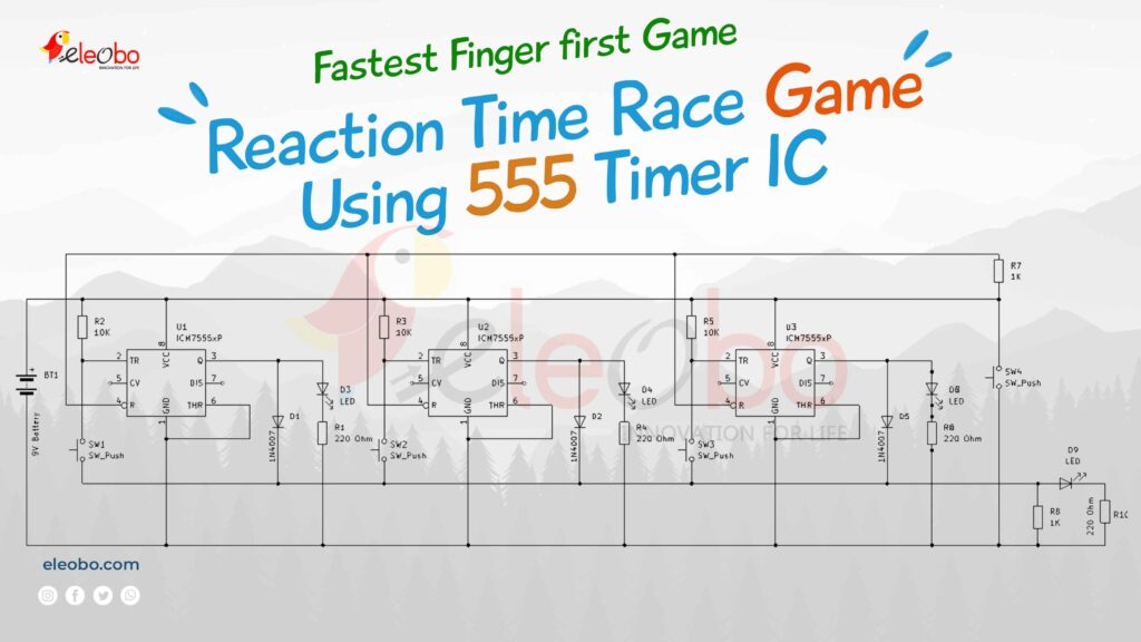
The Reaction Game Circuit relies on three 555 timer ICs, each controlling a player’s response. Let’s start with the first one:
- Connect Pin 6 and Pin 1 of the 555 timer IC to the ground (GND).
- Link Pin 2 and Pin 8 using a 10k resistor.
- Connect Pin 3 to the positive terminal of a 1N4007 diode and the positive terminal of an LED.
- Attach the negative terminal of the LED to GND through a 220-ohm resistor.
- Connect the negative terminal of the diode to one pin of a 2-pin push button.
- Link the other pin of the push button to Pin 2 of the 555 timer IC.
- Finally, connect Pin 8 to the VCC (positive power supply).
This setup ensures that when the push button is pressed, the LED lights up, indicating a player’s reaction.
Step 2: Repeating the Setup for the Remaining 555 Timers
The beauty of the Reaction Game Circuit lies in its scalability. Repeat the exact same setup for the second and third 555 timer ICs. Each IC will control a separate player’s response, ensuring a fair and competitive game.
Step 3: Adding the Reset Functionality
To make the Reaction Game Circuit reusable, we need to add a reset button:
- Connect the Pin 4 of all three 555 timer ICs to one pin of the fourth push button (the reset button).
- Link the other pin of the reset button to GND.
- Connect the push buttons of all three players to GND through a 1k resistor.
- Add a status LED by connecting its positive terminal to the status rail (or the push button pin) and its negative terminal to GND through a 220-ohm resistor.
This reset button ensures that the game can be restarted quickly, making it ready for the next round of competition.
Step 4: Testing the Circuit
Once all connections are made, it’s time to test your Reaction Game Circuit:
- Power up the circuit using a 5V-9V power supply.
- Press the reset button to initialize the game.
- When the signal (LED) lights up, players must press their buttons as quickly as possible.
- The first player to press their button will light up their LED, indicating the winner.
Physics Behind Each Component
1. 555 Timer IC
The 555 timer IC is the heart of the Reaction Game Circuit. It operates in three modes: monostable, astable, and bistable. In this project, we use it in monostable mode, where it produces a single pulse when triggered.
- How It Works:
- When the trigger pin (Pin 2) receives a low signal (from the push button), the output pin (Pin 3) goes high for a duration determined by the resistor and capacitor connected to Pin 6 and Pin 7.
- The formula for the pulse duration is:
T = 1.1 \times R \times C
Where ( R ) is the resistor value and ( C ) is the capacitor value. - Role in the Circuit:
- The 555 timer acts as a delay mechanism. When a player presses their button, the timer triggers, lighting up their LED and locking out other players.
2. Push Buttons
Push buttons are mechanical switches that complete or break a circuit when pressed.
- How It Works:
- When the button is pressed, it connects two terminals, allowing current to flow.
- In the Reaction Game Circuit, pressing the button sends a low signal to the 555 timer’s trigger pin, activating the timer.
- Role in the Circuit:
- Each player’s push button acts as the input trigger for their respective 555 timer.
3. LEDs (Light Emitting Diodes)
LEDs are semiconductor devices that emit light when current flows through them.
- How It Works:
- LEDs have a forward voltage drop (typically 1.8V-3.3V) and require a current-limiting resistor to prevent damage.
- In the circuit, the 220-ohm resistor ensures the LED receives the correct current.
- Role in the Circuit:
- LEDs indicate which player pressed their button first, providing visual feedback.
4. 1N4007 Diodes
Diodes are semiconductor devices that allow current to flow in one direction only.
- How It Works:
- The 1N4007 diode has a forward voltage drop of about 0.7V and is used to prevent reverse current flow.
- In the circuit, it ensures that the signal from the push button only affects the corresponding 555 timer.
- Role in the Circuit:
- The diode isolates each player’s circuit, preventing interference between players.
5. Resistors
Resistors limit the flow of current in a circuit.
- How It Works:
- Ohm’s Law (( V = IR )) governs the relationship between voltage, current, and resistance.
- In the circuit, resistors are used to:
- Limit current to the LEDs (220-ohm resistors).
- Set the timing for the 555 timer (10k resistors).
- Pull down the push button signals (1k resistors).
- Role in the Circuit:
- Resistors ensure proper operation of the LEDs and 555 timers.
How the 555 Timer Works in the Reaction Game Circuit
The 555 timer IC is configured in monostable mode for this project. Here’s how it operate:
- Initial State: The output (Pin 3) is low, and the capacitor is discharged.
- Triggering: When a player presses their button, the trigger pin (Pin 2) receives a low signal, activating the timer.
- Output Pulse: The output goes high for a duration determined by the resistor and capacitor connected to Pin 6 and Pin 7.
- Reset: The reset button discharges the capacitor, returning the timer to its initial state.
Conclusion
Building a Reaction Game Circuit is an exciting and rewarding project that combines electronics with fun. By following this guide, you’ve created a game that tests reflexes, encourages competition, and introduces you to the world of circuitry. Whether you’re a beginner or an experienced hobbyist, this project is a fantastic way to hone your skills and impress your friends. So, what are you waiting for? Gather your components, follow the steps, and get ready to build the ultimate Reaction Game Circuit!
Final Thoughts
The Reaction Game Circuit is more than just a project; it’s a testament to the power of creativity and electronics. With its simple yet effective design, it’s a perfect example of how technology can be both educational and entertaining. So, dive in, experiment, and enjoy the thrill of creating something truly unique.
By following this guide, you’ve not only built a Reaction Game Circuit but also gained valuable insights into electronics. Now, it’s time to challenge your friends and see who has the fastest reflexes!
Download BlueBot Controller App and start your journey today!