Gyroscopes have always been fascinating, especially as kids when we saw them at science fairs. They moved in unexpected ways, almost like they were defying gravity. Because of their special properties, gyroscopes are used in many devices, from small RC helicopters to advanced space shuttle navigation systems.
In recent years, engineers have created tiny micromachined gyroscopes called MEMS (Microelectromechanical System) gyroscopes. These have made many new technologies possible, such as gesture control, better gaming experiences, augmented reality, panoramic photography, vehicle navigation, and fitness tracking.
However, gyroscopes alone cannot provide complete motion data. That’s where the MPU6050 Accelerometer comes in. It combines both a gyroscope and an accelerometer in a single chip, allowing it to measure rotation, movement, and even gravity. Because of this, the MPU6050 Accelerometer is widely used in projects that need accurate motion sensing.
When an MPU6050 Accelerometer is connected to an Arduino, it can track how an object moves and tilts in real-time. This makes it useful for robots, drones, and even fitness devices. Before using the MPU6050 Accelerometer in a project, it’s important to understand how gyroscopes and accelerometers work together to measure motion and orientation.
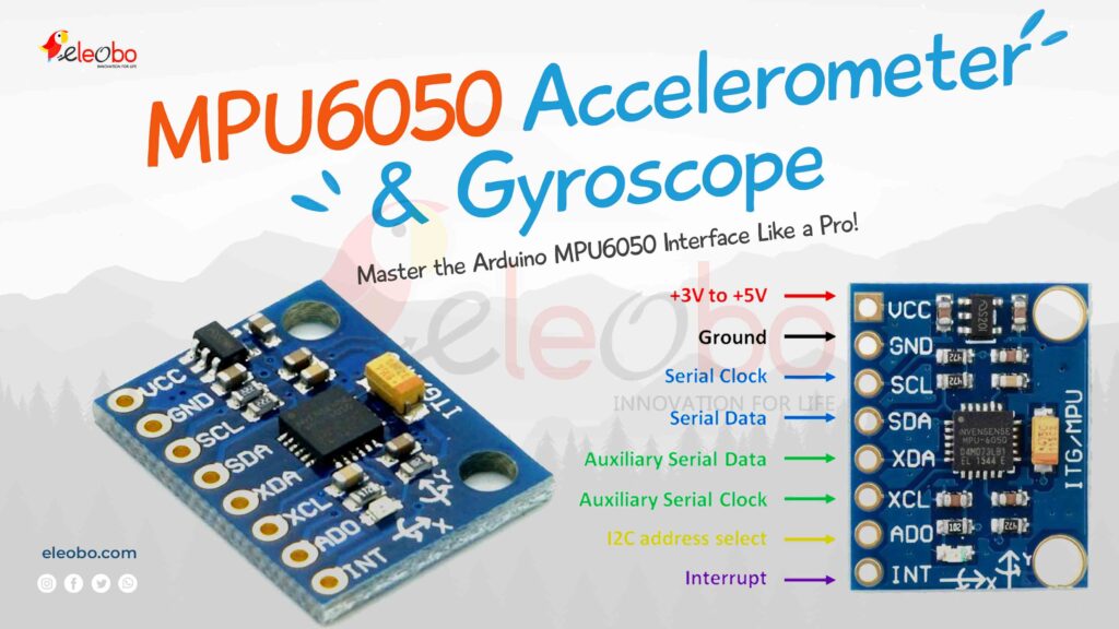
Table of Contents
What is the MPU6050 Accelerometer and Gyroscope?
The MPU6050 Accelerometer and Gyroscope is a 6-axis motion tracking sensor that integrates a 3-axis accelerometer and a 3-axis gyroscope into a single compact module. It is widely used in motion-based applications, robotics, drones, gaming controllers, and wearable devices due to its high precision and ease of integration with microcontrollers like Arduino and Raspberry Pi.
Features of the MPU6050 Sensor
Key Features of a 6 DOF IMU Sensor (e.g., MPU6050)
1. 6 Degrees of Freedom (DOF)
- “Degrees of Freedom” (DOF) refers to the number of independent movements a sensor can measure.
- A 6 DOF sensor can measure motion in six directions:
- Three linear movements (forward/backward, left/right, up/down) detected by the accelerometer.
- Three rotational movements (pitch, roll, and yaw) detected by the gyroscope.
- This makes it useful for applications like robotics, drones, and motion tracking.
2. 3-Axis Accelerometer
- Measures linear acceleration along three axes:
- X-axis (left to right movement)
- Y-axis (forward and backward movement)
- Z-axis (up and down movement)
- It helps detect movement, tilt, and orientation changes.
- Used in applications like motion control, gaming, and smartphone screen rotation.
3. 3-Axis Gyroscope
- Measures angular velocity (how fast an object is rotating) around three axes:
- X-axis (roll): Rotation around the horizontal axis.
- Y-axis (pitch): Rotation around the vertical axis.
- Z-axis (yaw): Rotation around the front-to-back axis.
- Useful in stabilization systems, VR headsets, drones, and robotics.
4. I2C Communication
- The sensor uses I2C (Inter-Integrated Circuit) protocol to communicate with microcontrollers like Arduino, ESP32, or Raspberry Pi.
- I2C allows multiple devices to connect using just two wires (SDA – Data, SCL – Clock), reducing wiring complexity.
5. Embedded Digital Motion Processor (DMP)
- The DMP is an onboard processor that helps process motion data before sending it to the main microcontroller.
- It reduces the computational load on the microcontroller, making motion tracking more efficient.
- Useful for real-time applications like gaming, gesture control, and autonomous vehicles.
6. Low Power Consumption
- Designed to consume very little power, making it ideal for battery-powered devices like wearable gadgets, wireless controllers, and IoT sensors.
- Helps extend battery life in portable applications.
7. Built-in Temperature Sensor
- Measures ambient temperature inside the sensor.
- While not highly accurate, it can be useful for compensating sensor drift due to temperature changes.
Where MPU6050 Sensor is it Used?
- Drones & Robotics – For motion tracking and stabilization.
- Virtual Reality (VR) & Gaming – For detecting head movements and gestures.
- Wearable Tech – In smartwatches and fitness trackers.
- Self-Balancing Vehicles – Like Segways and robotic cars.
- Smartphones & Tablets – For auto-rotation and motion-based apps.
Difference Between Gyroscope and Accelerometer
Motion sensors like gyroscopes and accelerometers play a crucial role in detecting movement and orientation in various devices, from smartphones to drones. While both measure motion, they work differently and serve distinct purposes. The table below highlights their key differences:
| Feature | Gyroscope | Accelerometer |
|---|---|---|
| Measures | Rotation (angular velocity) | Acceleration (linear motion) |
| Detects | Orientation change, spinning, and angular movement | Movement, tilt, and vibration |
| Axes | X, Y, Z (rotational) | X, Y, Z (linear) |
| Works on | Coriolis effect (detects angular movement) | Seismic mass and capacitance change |
| Can detect tilt? | No, but it detects rotation | Yes, because it senses gravitational acceleration |
| Can detect motion? | Only rotational motion | Yes, both static (gravity) and dynamic motion |
| Example Uses | Drones, gaming controllers, smartphones (screen rotation) | Step counters, vehicle acceleration, fall detection |
| Data Output | Measures rotational speed in degrees per second (°/s) | Measures acceleration in meters per second squared (m/s²) |
| Best For | Stabilization, orientation tracking | Motion detection, tilt sensing |
How the MPU6050 Accelerometer and Gyroscope Work
The accelerometer in the MPU6050 Accelerometer measures linear acceleration and tilt by detecting changes in motion and converting them into electrical signals. It works based on the principle of inertia, where tiny internal weights (seismic masses) move in response to motion or tilt, altering electrical properties that are then measured.
1.2 Detailed Breakdown of the Accelerometer
1.2.1 Inside the Accelerometer: The Tiny Weights (Seismic Masses)
- The MPU6050 Accelerometer contains small structures called seismic masses (or proof masses).
- These masses are made of silicon and fabricated using MEMS (Micro-Electro-Mechanical Systems) technology.
- They are suspended by thin silicon springs, allowing them to move slightly when the sensor experiences motion or tilt.
1.2.2 Movement of the Weights
1. When the Sensor is Stationary
- When the sensor is at rest, the seismic masses remain in their neutral or equilibrium position.
- This is because no external force (other than gravity) is acting upon them.
- The sensor registers a constant acceleration due to Earth’s gravity (typically 9.81 m/s² on the Z-axis if the sensor is positioned flat).
2. When the Sensor Moves or Tilts
The seismic masses respond to motion or changes in orientation due to inertia, which is the resistance of an object to changes in its motion.
a) Tilting the Sensor (Static Acceleration)
- When the sensor is tilted, the seismic masses shift due to the force of gravity pulling them in a new direction.
- This shift is detected as a change in acceleration along the corresponding axis (X, Y, or Z).
- For example, if the sensor is tilted forward, the X-axis reading may increase while the Z-axis reading decreases.
b) Shaking or Moving the Sensor (Dynamic Acceleration)
- When the sensor experiences sudden motion (such as shaking or rapid movement), the seismic masses move in the opposite direction of the acceleration due to inertia.
- This occurs because the masses want to remain in their initial state while the sensor moves around them.
- The displacement of these masses is measured and converted into electrical signals, which the sensor interprets as acceleration data.
3. Axis-Specific Motion Detection
A typical 3-axis motion sensor detects movement along three perpendicular axes:
- X-axis: Left and right movement
- Y-axis: Forward and backward movement
- Z-axis: Up and down movement
Each seismic mass inside the sensor corresponds to one of these axes. The movement of these masses relative to their neutral positions allows the sensor to determine the direction and intensity of motion.
1.2.3 Converting Motion into an Electrical Signal
1. Role of Capacitive Sensing in the MPU6050 Accelerometer
- Inside the sensor, there are tiny seismic masses that move when the device tilts or accelerates.
- These masses are suspended between capacitor plates that are fixed within the sensor.
- The distance between the plates and the seismic mass determines the capacitance value.
2. How Movement Affects Capacitance
- When the sensor moves, the seismic masses shift due to inertia.
- This causes the distance between the capacitor plates to increase or decrease, which alters the capacitance.
- A larger gap decreases capacitance, while a smaller gap increases it.
3. Conversion of Capacitance to Voltage
- The MPU6050 detects these capacitance changes and converts them into corresponding voltage signals.
- The voltage level represents the acceleration or tilt of the sensor along the X, Y, and Z axes.
4. Analog-to-Digital Conversion (ADC) in the MPU6050
- The generated voltage signals are still in analog form, which microcontrollers like Arduino cannot directly process.
- The MPU6050 Accelerometer includes an Analog-to-Digital Converter (ADC) that transforms the voltage signals into digital data.
- This digital data is then sent to a microcontroller (e.g., Arduino) via the I2C communication protocol.
5. Reading Data from the MPU6050 Using an Arduino
- The microcontroller reads the digital acceleration and gyroscope values from the MPU6050 Accelerometer.
- These values help determine motion, tilt, and orientation of the sensor in real-time.
- The data can be used for applications like robotics, gaming controllers, drones, and motion tracking systems.
1.2.4 Processing the Data
The MPU6050 Accelerometer is a 6-axis motion sensor that detects movement and orientation. It processes data using its built-in accelerometer and gyroscope to determine motion in real-time.
1. Acceleration Along Three Axes (X, Y, Z)
- The MPU6050 Accelerometer measures acceleration along the X, Y, and Z axes.
- Each axis represents movement in a specific direction:
- X-axis: Left and right motion
- Y-axis: Forward and backward motion
- Z-axis: Up and down motion
2. Tilt Angle Measurement
- The MPU6050 Accelerometer detects tilt angle, which indicates how much the sensor is leaning in a particular direction.
- This is useful for applications like balancing robots, drone stabilization, and motion tracking.
- The tilt is calculated based on the acceleration values from the X, Y, and Z axes.
3. Static Acceleration (Gravity-Based Acceleration)
- Static acceleration occurs when the sensor is tilted but not moving.
- The MPU6050 Accelerometer detects this acceleration due to gravity.
- For example, if the sensor is held at an angle, it will measure a steady acceleration along a certain axis, even though there is no physical movement.
- This data is useful for detecting orientation changes, such as in smartphone screen rotation and game controllers.
4. Dynamic Acceleration (Motion-Based Acceleration)
- Dynamic acceleration is caused by active movement such as shaking, jumping, or rapid directional changes.
- The MPU6050 Accelerometer detects these sudden movements by tracking changes in acceleration over time.
- This is useful for applications like gesture control, fall detection, and fitness tracking.
1.3 Applications of the Accelerometer
- Detecting tilt and orientation.
- Measuring acceleration in motion-based applications.
- Step counting (pedometers).
- Balancing systems in robots and drones.
2. How the MPU6050 Gyroscope Works
2.1 Basic Working Principle
The gyroscope in the MPU6050 measures angular velocity (rotation speed) around the X, Y, and Z axes. It detects changes in orientation using the Coriolis Effect, where vibrating masses inside the sensor experience a force when rotated.
2.2 Detailed Breakdown of the Gyroscope
2.2.1 Inside the Gyroscope: Vibrating Masses
- The gyroscope contains tiny vibrating masses that oscillate at a fixed frequency.
- These masses are suspended using MEMS technology, similar to the accelerometer’s seismic masses.
2.2.2 How Rotation is Detected
- When the MPU6050 rotates, the vibrating masses experience a force called the Coriolis force, which acts perpendicular to their motion.
- This force causes a shift in the vibration pattern of the masses.
- The shift is detected by internal capacitive sensors, similar to the accelerometer’s working principle.
2.2.3 Converting Rotation into an Electrical Signal
- The MPU6050 measures the shift in vibration caused by the Coriolis force.
- This shift alters capacitance, generating voltage signals that correspond to rotational movement.
- An Analog-to-Digital Converter (ADC) inside the MPU6050 converts these voltage signals into digital data.
- The data is processed to calculate angular velocity (how fast the device is rotating) along three axes:
- X-axis: Roll (left-right tilt).
- Y-axis: Pitch (forward-backward tilt).
- Z-axis: Yaw (rotation around the vertical axis).
2.3 Applications of the Gyroscope
- Measuring rotational movements in drones and robots.
- Motion sensing in gaming controllers.
- Stabilization in cameras (gimbal systems).
- Navigation systems in mobile devices.
3. Roll, Pitch, and Yaw – Understanding Orientation
3.1 Definition of Roll, Pitch, and Yaw
The MPU6050 measures motion in three rotational axes, commonly referred to as Roll, Pitch, and Yaw:
- Roll (Rotation around the X-axis): Tilting left or right (like a plane rolling side to side).
- Pitch (Rotation around the Y-axis): Tilting forward or backward (like nodding your head).
- Yaw (Rotation around the Z-axis): Rotating left or right (like turning a steering wheel).
3.2 Why Roll, Pitch, and Yaw Matter
- Used in drones to maintain stability.
- Helps robots understand their orientation.
- Essential for Virtual Reality (VR) head tracking.
Wiring the MPU6050 Module to an Arduino
Connecting the MPU6050 Module to an Arduino is simple. Follow these steps:
- Connect VCC to the 3.3V or 5V pin on the Arduino.
- Connect GND to the GND pin.
- Connect SCL to the A5 pin (or the SCL pin on Arduino Uno).
- Connect SDA to the A4 pin (or the SDA pin on Arduino Uno).
The Arduino MPU6050 Interface uses the I2C protocol, making it easy to communicate with the sensor.
Installing the MPU6050 Library
To use the MPU6050 Accelerometer and Gyroscope with Arduino, you’ll need the Adafruit MPU6050 library. Here’s how to install it:
- Open the Arduino IDE.
- Go to Sketch > Include Library > Manage Libraries.
- Search for “Adafruit MPU6050” and install the library.
- Install the Adafruit Sensor library as well, as it’s a dependency.
Writing Code for the MPU6050 Accelerometer and Gyroscope
Here’s a basic example to get you started with the MPU6050 Module:
#include <Adafruit_MPU6050.h>
#include <Adafruit_Sensor.h>
#include <Wire.h>

Adafruit_MPU6050 mpu;

void setup(void) {
  Serial.begin(115200);

  // Try to initialize!
  if (!mpu.begin()) {
    Serial.println("Failed to find MPU6050 chip");
    while (1) {
      delay(10);
    }
  }
  Serial.println("MPU6050 Found!");

  // Set accelerometer range to ±8G
  mpu.setAccelerometerRange(MPU6050_RANGE_8_G);

  // Set gyro range to ±500 deg/s
  mpu.setGyroRange(MPU6050_RANGE_500_DEG);

  // Set filter bandwidth to 21 Hz
  mpu.setFilterBandwidth(MPU6050_BAND_21_HZ);

  delay(100);
}

void loop() {
  // Get new sensor events
  sensors_event_t a, g, temp;
  mpu.getEvent(&a, &g, &temp);

  // Print acceleration values
  Serial.print("Acceleration X: ");
  Serial.print(a.acceleration.x);
  Serial.print(", Y: ");
  Serial.print(a.acceleration.y);
  Serial.print(", Z: ");
  Serial.print(a.acceleration.z);
  Serial.println(" m/s^2");

  // Print rotation values
  Serial.print("Rotation X: ");
  Serial.print(g.gyro.x);
  Serial.print(", Y: ");
  Serial.print(g.gyro.y);
  Serial.print(", Z: ");
  Serial.print(g.gyro.z);
  Serial.println(" rad/s");

  // Print temperature
  Serial.print("Temperature: ");
  Serial.print(temp.temperature);
  Serial.println(" degC");

  Serial.println("");
  delay(500);
}
This code reads data from the MPU6050 Accelerometer and Gyroscope and prints it to the Serial Monitor.
Plotting MPU6050 Data
To visualize the data, you can use the Arduino Serial Plotter. Modify the code to output comma-separated values:
void loop() {
  sensors_event_t a, g, temp;
  mpu.getEvent(&a, &g, &temp);

  Serial.print(a.acceleration.x);
  Serial.print(",");
  Serial.print(a.acceleration.y);
  Serial.print(",");
  Serial.print(a.acceleration.z);
  Serial.print(", ");
  Serial.print(g.gyro.x);
  Serial.print(",");
  Serial.print(g.gyro.y);
  Serial.print(",");
  Serial.print(g.gyro.z);
  Serial.println("");

  delay(10);
}
Open the Serial Plotter in the Arduino IDE to see real-time graphs of the sensor data.
Applications of the MPU6050 Accelerometer and Gyroscope
The MPU6050 Module is used in a wide range of applications, including:
- Robotics: For balancing and navigation.
- Drones: For flight stabilization.
- Wearable Devices: For fitness tracking.
- Gaming: For motion-controlled games.
- Augmented Reality: For head tracking.
Why Choose the MPU6050 Module?
The MPU6050 Accelerometer and Gyroscope is a versatile and affordable sensor that offers exceptional performance. Its Arduino MPU6050 Interface makes it easy to integrate into your projects, while its compact design ensures it fits into even the smallest devices.
Conclusion
The MPU6050 Accelerometer and Gyroscope is a must-have sensor for anyone working on motion-sensing projects. With its Arduino MPU6050 Interface and powerful features, the MPU6050 Module opens up endless possibilities for innovation.
So, what are you waiting for? Grab a MPU6050 Module, connect it to your Arduino, and start building something amazing today!
Download BlueBot Controller App and start your journey today!