In today’s fast-paced world, safety and innovation go hand in hand. The Auto Braking Arduino Project is a perfect example of how technology can enhance safety in everyday applications. This project leverages the power of Arduino, an L298N motor driver, PWM (Pulse Width Modulation), and a DC gear motor to create an auto-braking system that mimics the functionality of an Anti-lock Braking System (ABS). Whether you’re a hobbyist, a student, or a tech enthusiast, this project will not only teach you valuable skills but also inspire you to create smarter, safer systems. Let’s dive into the details of this exciting Auto Braking Arduino Project!
Table of Contents
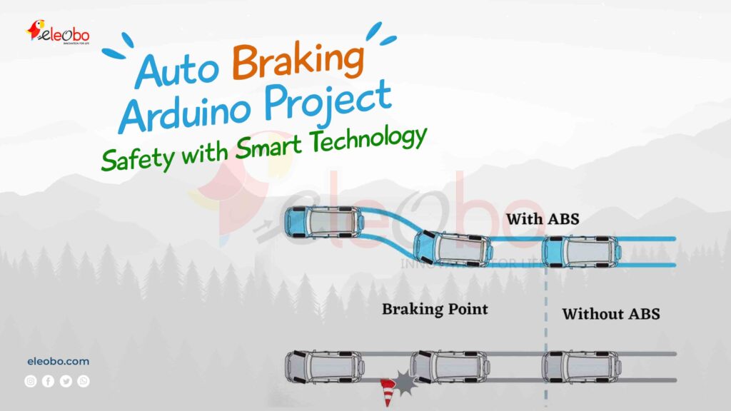
Why the Auto Braking Arduino Project Matters
The Auto Braking Arduino Project is more than just a technical experiment; it’s a step toward creating safer systems for vehicles, robotics, and industrial applications. By integrating an L298N motor driver and PWM, this project allows you to control the speed of a DC gear motor and implement an auto-braking mechanism that prevents sudden stops, just like ABS in modern cars. This project is not only educational but also highly practical, making it a must-try for anyone interested in embedded systems and automation.
Components Needed for the Auto Braking Arduino Project
To build the Auto Braking Arduino Project, you’ll need the following components:
- Arduino Uno – The brain of the project.
- L298N Motor Driver – Controls the direction and speed of the DC gear motor.
- DC Gear Motor – Provides the motion for the system.
- PWM (Pulse Width Modulation) – Regulates the motor speed.
- Ultrasonic Sensor (HC-SR04) – Detects obstacles and triggers the auto-braking system.
- Breadboard and Jumper Wires – For easy connections.
- Power Supply (9V Battery or DC Adapter) – Powers the motor and Arduino.
- Push Button – Acts as a manual brake trigger.
- LEDs (Optional) – For visual feedback.
- Resistors (220Ω) – For LED current limiting.
How the Auto Braking Arduino Project Works
The Auto Braking Arduino Project works by combining the power of an Arduino, an L298N motor driver, and an ultrasonic sensor. Here’s how it functions:
- The ultrasonic sensor continuously measures the distance between the system and any obstacle.
- When the sensor detects an obstacle within a predefined range, it sends a signal to the Arduino.
- The Arduino processes this signal and uses PWM to gradually reduce the speed of the DC gear motor via the L298N motor driver.
- The motor slows down and eventually stops, mimicking the behavior of an ABS system.
- If the obstacle is removed, the system resumes normal operation.
This process ensures smooth and safe braking, preventing sudden stops that could cause damage or accidents.
Step-by-Step Connections for the Auto Braking Arduino Project
Let’s connect the components for the Auto Braking Arduino Project:
- Arduino and L298N Motor Driver:
- Connect the IN1 and IN2 pins of the L298N to D8 and D9 of the Arduino.
- Connect the ENA pin of the L298N to D6 (PWM pin) on the Arduino.
- Connect the GND and VCC of the L298N to the Arduino’s GND and 5V pins.
- DC Gear Motor and L298N:
- Connect the motor terminals to the OUT1 and OUT2 pins of the L298N.
- Ultrasonic Sensor and Arduino:
- Connect the Trig pin of the HC-SR04 to D2 and the Echo pin to D3.
- Connect the VCC and GND of the sensor to the Arduino’s 5V and GND.
- Push Button and Arduino:
- Connect one terminal of the push button to D4 and the other to GND.
- Power Supply:
- Connect the 12V terminal of the L298N to the positive terminal of the power supply.
- Connect the GND of the L298N to the negative terminal of the power supply.
DC Gear Motor
A DC Gear Motor is a type of direct current (DC) motor that comes with a built-in gear mechanism. The gear mechanism reduces the speed of the motor’s output while increasing its torque. This makes DC gear motors ideal for applications where you need precise control over the movement, like in robotics or other mechanical systems that require more power at lower speeds.
L298N
The L298N is a dual H-Bridge motor driver used to control DC motors, stepper motors, and other inductive loads. It allows you to control the direction and speed of the motor by supplying current to the motor. The L298N can handle two DC motors at the same time and can be used with microcontrollers like Arduino to control motors for various projects like robots, automated systems, and more.
Ultrasonic Sensor: What It Is and How It Works
The ultrasonic sensor is a versatile and widely used electronic device that measures distance using sound waves. It’s a key component in many projects, including robotics, automation, and safety systems like the Auto Braking Arduino Project. But what exactly is an ultrasonic sensor, and how does it work? Let’s dive into the details and explore this fascinating technology.
What Is an Ultrasonic Sensor?
An ultrasonic sensor is an electronic device that uses ultrasonic waves (sound waves with frequencies higher than the human hearing range, typically 40 kHz) to measure the distance between the sensor and an object. It consists of two main components:
- Transmitter: Emits ultrasonic sound waves.
- Receiver: Detects the reflected sound waves after they bounce off an object.
The sensor calculates the time it takes for the sound waves to travel to the object and back, and then uses this information to determine the distance. Ultrasonic sensors are known for their accuracy, reliability, and ability to work in various environments, making them ideal for applications like obstacle detection, level measurement, and proximity sensing.
How Does an Ultrasonic Sensor Work?
The working principle of an ultrasonic sensor is based on the echo-ranging technique. Here’s a step-by-step explanation of how it works:
1. Transmitting Ultrasonic Waves
The transmitter in the ultrasonic sensor emits high-frequency sound waves (typically 40 kHz) in a specific direction. These sound waves are inaudible to humans and travel through the air at the speed of sound (approximately 343 meters per second at room temperature).
2. Reflecting Off an Object
When the ultrasonic waves encounter an object in their path, they bounce back (reflect) toward the sensor. The surface of the object must be solid enough to reflect the sound waves effectively.
3. Receiving the Reflected Waves
The receiver in the ultrasonic sensor detects the reflected sound waves. The sensor measures the time interval between the emission of the sound waves and their return to the receiver. This time interval is called the time of flight.
4. Calculating the Distance
Using the time of flight and the speed of sound, the sensor calculates the distance to the object using the following formula:
Distance =Speed of Sound × Time of Flight / 2
The division by 2 is necessary because the sound waves travel to the object and back, covering twice the distance.
Code for the Auto Braking Arduino Project
Here’s the Arduino code for the Auto Braking Arduino Project:
// Define pins
const int trigPin = 2;
const int echoPin = 3;
const int in1 = 8;
const int in2 = 9;
const int enA = 6;
const int brakeButton = 4;

int motorSpeed = 255; // Initial motor speed (max speed)
int distanceThreshold = 20; // Distance threshold in cm

void setup() {
  pinMode(trigPin, OUTPUT);
  pinMode(echoPin, INPUT);
  pinMode(in1, OUTPUT);
  pinMode(in2, OUTPUT);
  pinMode(enA, OUTPUT);
  pinMode(brakeButton, INPUT_PULLUP);
  Serial.begin(9600);
}

void loop() {
  // Measure distance
  long duration, distance;
  digitalWrite(trigPin, LOW);
  delayMicroseconds(2);
  digitalWrite(trigPin, HIGH);
  delayMicroseconds(10);
  digitalWrite(trigPin, LOW);
  duration = pulseIn(echoPin, HIGH);
  distance = (duration / 2) / 29.1;

  // Check if obstacle is within threshold
  if (distance <= distanceThreshold) {
    autoBrake();
  } else {
    moveForward();
  }

  // Manual brake using push button
  if (digitalRead(brakeButton) == LOW) {
    stopMotor();
  }
}

void moveForward() {
  digitalWrite(in1, HIGH);
  digitalWrite(in2, LOW);
  analogWrite(enA, motorSpeed);
}

void autoBrake() {
  // Gradually reduce speed
  for (int i = motorSpeed; i >= 0; i--) {
    analogWrite(enA, i);
    delay(50);
  }
  stopMotor();
}

void stopMotor() {
  digitalWrite(in1, LOW);
  digitalWrite(in2, LOW);
  analogWrite(enA, 0);
}
Applications of the Auto Braking Arduino Project
The Auto Braking Arduino Project has numerous real-world applications:
- Automotive Safety: Mimics ABS in vehicles to prevent skidding and ensure safe braking.
- Robotics: Enhances the safety of autonomous robots by preventing collisions.
- Industrial Automation: Protects machinery and equipment from damage due to sudden stops.
- Smart Toys: Adds a layer of safety to remote-controlled cars and drones.
- Education: Serves as an excellent teaching tool for understanding PWM, motor control, and sensor integration.
Conclusion
The Auto Braking Arduino Project is a fantastic way to explore the intersection of safety and technology. By using an Arduino, an L298N motor driver, PWM, and a DC gear motor, you can create a system that not only works efficiently but also teaches you valuable skills in embedded systems and automation. Whether you’re building this for fun, education, or practical use, the Auto Braking Arduino Project is sure to leave you inspired and eager to take on more challenges. So, gather your components, follow the steps, and start building your own Auto Braking Arduino Project today!
By now, you’ve learned everything you need to know about the Auto Braking Arduino Project. From components and connections to coding and applications, this project is a gateway to endless possibilities. Don’t wait—start your journey into the world of smart technology today!
Download BlueBot Controller App and start your journey today!