Table of Contents
Introduction
Have you ever asked yourself, “How does a magnet turn on an LED without touching anything?” The answer lies in a simple but brilliant design called the LM741 op-amp reed switch LED circuit. This circuit uses three everyday components — a reed switch, an LM741 op-amp, and a 5mm LED — and brings them together in a way that responds instantly to magnetic fields.
If you are a student, a hobbyist, or a working engineer, this circuit gives you a solid foundation for understanding comparators, proximity sensing, and signal switching. Furthermore, once you understand how this design works, you can apply the same thinking to hundreds of other real-world projects.
So, in this blog, you will learn exactly what an LM741 op-amp reed switch LED circuit does, how each part contributes to the result, and how you can build and upgrade it yourself. Let us get started.
Frequently Asked Questions Before We Begin
What does an LM741 op-amp reed switch LED circuit do? It detects a magnetic field using a reed switch and uses the LM741 op-amp to turn on an LED whenever the magnetic field is present.
Is this circuit good for beginners? Yes, absolutely. It uses affordable, widely available components and teaches core electronics concepts like voltage comparison and current limiting.
What is the cost of building this circuit? The total cost of components is typically under $2 USD, making it one of the most budget-friendly learning circuits available.
Can this circuit work without the LM741? You could use other op-amps, but the LM741 is the best starting point because it is widely available, easy to source, and well-documented.
1. What Is an LM741 Op-Amp Reed Switch LED Circuit and Why Does It Matter?
Before we go further, let us be completely clear about what this circuit actually does. The LM741 op-amp reed switch LED circuit is a magnetic proximity detector. It uses the LM741 op-amp as a comparator that compares two voltages and switches its output based on which one is higher.
Here is the simple version: when no magnet is nearby, the LED stays off. When a magnet comes close to the reed switch, the circuit detects the change and turns the LED on. That is it — clean, fast, and reliable.
This matters because proximity detection appears in almost every area of electronics. Security systems, robotics, industrial automation, and consumer gadgets all rely on circuits that sense position or presence. The LM741 op-amp reed switch LED circuit teaches you the fundamental logic behind all of these systems using just a handful of affordable parts.
Furthermore, because the circuit uses an op-amp as a comparator rather than a dedicated IC, you gain a much deeper understanding of how op-amps actually behave in real circuits. That understanding serves you well as you move on to more advanced designs.
2. How Does the LM741 Op-Amp Reed Switch LED Circuit Actually Work?
Now, let us walk through the operation step by step so that everything makes complete sense.
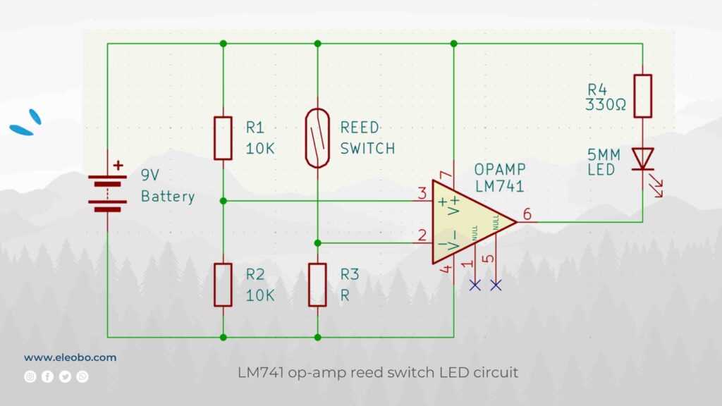
Step 1 — Power the Circuit First, you connect the 9V battery. The positive terminal connects to pin 7 of the LM741, and the negative terminal connects to pin 4. Additionally, two 10KΩ resistors (R1 and R2) form a voltage divider between the supply and ground. Their midpoint connects to pin 3, the non-inverting input. With equal resistor values, this midpoint sits at exactly 4.5V.
Step 2 — Reed Switch Open, No Magnet Present When no magnet is nearby, the reed switch stays open. As a result, the voltage at pin 2 (the inverting input) rises toward the supply voltage through R3. Since pin 2 now carries a higher voltage than pin 3, the LM741 drives its output at pin 6 LOW. No current flows through the LED, so the LED stays off.
Step 3 — Magnet Comes Near As soon as a magnet approaches the reed switch, the two ferromagnetic reeds inside the glass envelope snap together and close the contact. This action pulls the voltage at pin 2 toward ground. Consequently, pin 2 now carries a lower voltage than pin 3.
Step 4 — Op-Amp Output Switches HIGH The LM741 detects that pin 3 is now higher than pin 2 and immediately switches its output at pin 6 HIGH. The output voltage rises close to the supply voltage.
Step 5 — LED Turns On The high output at pin 6 drives current through R4 (330Ω) and into the anode of the 5mm LED. The LED lights up brightly. Moreover, it stays on for as long as the magnet remains near the reed switch.
Step 6 — Magnet Removed The moment the magnet moves away, the reed switch opens, pin 2 voltage rises again, the op-amp output goes LOW, and the LED turns off. This whole sequence happens in microseconds.
That is the complete working principle of the LM741 op-amp reed switch LED circuit explained in plain, human language — no jargon, no confusion.
3. What Does Each Component Do? A Clear Breakdown
Many people search for “what does each part do in an LM741 circuit” or “what is the role of R3 in a reed switch circuit?” So, let us answer those questions directly and clearly.
LM741 Op-Amp The LM741 is the brain of the LM741 op-amp reed switch LED circuit. It acts as a comparator, which means it looks at two input voltages and decides which one is higher. The output then goes HIGH or LOW based on that decision. The LM741 operates from a 9V single supply in this circuit and handles all the signal switching without any additional logic components.
Reed Switch The reed switch is the sensor. It detects the presence of a magnetic field and converts that physical event into an electrical signal. Unlike a push button, you never need to touch a reed switch to activate it. Therefore, you can seal it inside a casing and still trigger it remotely using a magnet.
R1 and R2 — 10KΩ Each These two resistors work together as a voltage divider. They set the reference voltage at pin 3 of the LM741. With both resistors at 10KΩ and a 9V supply, the reference sits at 4.5V. You can change this reference by swapping one of the resistors for a different value.
R3 — Variable or Fixed Resistor R3 controls the voltage level at pin 2 when the reed switch is open. It sets the sensitivity of the circuit by determining how far above the reference voltage pin 2 sits when no magnet is present. A lower R3 value makes the switch point more decisive.
R4 — 330Ω R4 protects the LED. It limits the current to approximately 21mA, which keeps the LED bright without damaging it. Always include this resistor. Skipping it will burn out the LED immediately.
5mm LED The LED is the output indicator. It gives you a clear, visible signal that the circuit has detected a magnetic field. You can replace it with a buzzer, relay, or any other output device depending on your application.
4. How to Calculate Component Values — Simple and Clear
Many beginners search for “how to calculate LED resistor value” or “how does a voltage divider work in an op-amp circuit.” Here are the answers in plain numbers.
Voltage Divider at Pin 3:
V_ref = Vcc × R2 ÷ (R1 + R2) V_ref = 9V × 10,000 ÷ (10,000 + 10,000) V_ref = 4.5V
This 4.5V reference is what the LM741 compares against pin 2. Moreover, if you want to change the threshold, simply use different resistor values in this formula.
LED Current Through R4:
I = (Vout − V_LED) ÷ R4 I = (9V − 2V) ÷ 330Ω I = 7V ÷ 330Ω ≈ 21mA
This current is safe and bright for a standard 5mm LED. Furthermore, if you use a red LED with a 1.8V forward voltage, the current increases slightly to about 21.8mA, which is still within safe limits.
Adjusting for a Different Supply Voltage: If you use 5V instead of 9V, adjust R4 accordingly:
I = (5V − 2V) ÷ R4 = 3V ÷ R4
For 15mA: R4 = 3V ÷ 0.015A = 200Ω
These calculations give you full control over every aspect of the LM741 op-amp reed switch LED circuit, so you never need to guess about component values.
5. Real-World Uses Where This Circuit Appears in Everyday Life
People often search for “where is a reed switch used in real life” or “practical applications of LM741 comparator.” Here are genuine, useful examples that go beyond the textbook.
Home Security and Door Alarms You can attach a magnet to a door or window and mount the reed switch on the fixed frame. When someone opens the door, the magnet moves away, the reed switch opens, and the LM741 op-amp reed switch LED circuit activates an LED or alarm. Consequently, you get a simple but effective intrusion alert with no complex programming required.
Industrial Part Detection on Conveyor Belts Factories use reed switches to detect the presence of ferromagnetic parts moving along a conveyor belt. The LM741 comparator circuit provides a clean output signal that machine controllers can read directly. As a result, the system counts parts, flags missing pieces, or triggers sorting mechanisms automatically.
Robotics End-Stop Sensing Builders of robotic arms and linear actuators use reed switches to detect end positions. When the moving part reaches a magnet placed at the limit, the LM741 op-amp reed switch LED circuit sends a signal to stop the motor. This prevents mechanical damage and gives precise position feedback without expensive encoders.
Tamper Detection in Enclosures Security products use this circuit to detect when someone opens a cover or housing. Place a magnet inside the lid and mount the reed switch inside the body. When the lid opens, the magnet separates, the circuit activates, and the tamper event is logged or alarmed. This method is used in everything from utility meters to safe deposit boxes.
Educational Lab Projects Teachers actively use the LM741 op-amp reed switch LED circuit to demonstrate voltage comparison, transistor-like switching, and Ohm’s Law all in one experiment. Students see the LED respond in real time, which makes abstract concepts click instantly.
6. Mistakes People Actually Make – and How to Avoid Them
Searching “why is my LM741 circuit not working” or “LED not lighting up in op-amp circuit” is very common. Here are the real reasons this circuit fails and exactly how to fix each one.
Mistake 1 — No Current-Limiting Resistor If you skip R4 and connect the LED straight to pin 6, the LED burns out within seconds. Always include a 330Ω or similar resistor between the output and the LED anode.
Mistake 2 — Wrong Pin Connections The LM741 pinout confuses many beginners. Pin 2 is the inverting input (−). Pin 3 is the non-inverting input (+). Pin 6 is the output. Pin 7 is V+ and pin 4 is V−. Always cross-check with the datasheet before powering up.
Mistake 3 — LED Connected Backwards A standard LED only conducts in one direction. If the anode connects toward ground, the LED will never light up regardless of how correct everything else is. Therefore, confirm the anode (+, longer leg) points toward the positive side of the circuit.
Mistake 4 — Magnet Too Weak or Too Far Reed switches need a minimum magnetic field strength to activate. A small fridge magnet held several centimeters away may not generate enough flux. Use a stronger neodymium magnet or place it closer. Furthermore, always test the reed switch on its own before blaming the rest of the circuit.
Mistake 5 — No Supply Decoupling Capacitor Without a 100nF ceramic capacitor placed directly between pin 7 and pin 4, high-frequency noise can cause the output to oscillate erratically. Add this capacitor to every LM741 circuit you build, especially on breadboards.
Avoiding these five mistakes means your first build of the LM741 op-amp reed switch LED circuit works correctly the first time.
7. How to Upgrade This Circuit – Go Further with the Same Concept
Once your basic LM741 op-amp reed switch LED circuit works, you will want to push it further. Here are practical upgrades that real builders use.
Add a Buzzer for Audio Output Connect a small buzzer in parallel with the LED to add an audible alert. If the buzzer draws more than 25mA, buffer the output with a BC547 NPN transistor to protect the LM741.
Add Hysteresis to Prevent Chattering In electrically noisy environments, the output can oscillate rapidly when the input voltage sits near the threshold. To fix this, connect a high-value resistor (around 1MΩ) from pin 6 back to pin 3. This creates a Schmitt trigger effect that snaps the output cleanly between states and eliminates false triggering completely.
Drive a Relay for High-Power Control Connect a transistor-driven relay to the output so that the circuit controls lamps, motors, or solenoids. The LM741 provides the decision signal, and the relay handles the heavy current. As a result, the LM741 op-amp reed switch LED circuit becomes the control center for a much larger system.
Chain Multiple Reed Switches Connect reed switches in series to require all switches to close before the LED activates. Alternatively, connect them in parallel so that any single switch triggers the output. This gives you multi-point detection from a single circuit.
Interface with a Microcontroller The LM741 output is fully compatible with Arduino, ESP32, and Raspberry Pi GPIO inputs. Therefore, you can use this circuit as a front-end sensor stage that feeds clean digital signals into a microcontroller for logging, automation, or IoT applications.
What Real Builders Say About This Circuit
Electronics community forums are full of positive feedback about this design. Hobbyists describe the LM741 op-amp reed switch LED circuit as “the circuit that made op-amps click for me” and “the best first comparator project for any beginner.” Students report that building this circuit in a single evening gave them a clearer understanding of voltage comparison than weeks of theory alone.
The reason is simple — this circuit delivers immediate, visible feedback. You build it, you hold a magnet near the reed switch, and the LED lights up. That direct cause-and-effect moment makes the theory real.
Conclusion – Build It, Learn It, Own It
The LM741 op-amp reed switch LED circuit is more than a beginner project. It is a foundation. Every concept you learn here — voltage division, comparator logic, current limiting, magnetic sensing — appears again and again in advanced circuit design.
You now understand what each component does and why it is there. You know how to calculate the correct values, how to read the schematic, how the circuit responds step by step, and how to avoid the mistakes that trip up most beginners. Furthermore, you know how to upgrade and extend this design into something genuinely powerful.
So, gather your components, follow the schematic, run through the calculations, and build your first LM741 op-amp reed switch LED circuit today. The moment that LED turns on in response to a magnet, you will know you understand comparators — and that knowledge will serve you for the rest of your electronics journey.
Go build it. The components are cheap, the concept is clear, and the result is deeply satisfying.
Visit : Home Page
LM741 Datasheet Download