If you’re new to electronics, learning how to read a datasheet can feel overwhelming. But don’t worry this guide will walk you through the process in a simple, beginner-friendly way. By the end, you’ll know exactly how to read a datasheet, specifically for the iconic 555 timer IC. Whether you’re building a simple LED flasher or a complex timing circuit, understanding how to read a datasheet is the key to success.
Let’s dive in and demystify the process of how to read a datasheet, using the 555 timer as our example.
Why Learning How to Read a Datasheet is Essential
Before we jump into the details, let’s talk about why learning how to read a datasheet is so important. A datasheet is like a user manual for electronic components. It contains all the technical information you need to use the component correctly and effectively. For the 555 timer, the datasheet includes pin configurations, electrical characteristics, timing equations, and example circuits.
By learning how to read a datasheet, you gain the confidence to work with any component, not just the 555 timer. It’s a skill that will serve you well throughout your electronics journey.
How to Read a Datasheet: Step-by-Step Breakdown
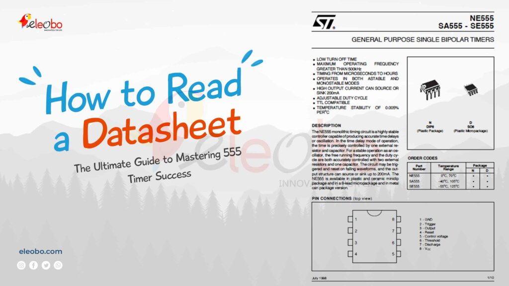
1. Start with the Pin Configuration
The first step in learning how to read a datasheet is understanding the pin configuration. This section shows you how the component is laid out and what each pin does. For the 555 timer, the pin configuration includes:
- Pin 1 (GND): Connects to the ground.
- Pin 2 (TRIG): Starts the timing cycle when triggered.
- Pin 3 (OUT): Delivers the output signal.
- Pin 4 (RESET): Resets the timer when pulled low.
- Pin 5 (CTRL): Allows external control of the timing.
- Pin 6 (THR): Ends the timing cycle when the threshold is reached.
- Pin 7 (DIS): Discharges the timing capacitor.
- Pin 8 (VCC): Connects to the positive supply voltage.
Understanding the pin configuration is the foundation of learning how to read a datasheet.
2. Study the Electrical Characteristics
Next, the datasheet provides electrical characteristics, which tell you how the component behaves under different conditions. For the 555 timer, this includes:
- Supply Voltage (VCC): Typically 4.5V to 16V.
- Output Current: The maximum current the output pin can handle.
- Power Consumption: How much power the IC uses during operation.
These details are crucial for ensuring your circuit works safely and efficiently.
3. Examine the Functional Block Diagram
The functional block diagram is a visual representation of the 555 timer’s internal circuitry. It includes components like comparators, flip-flops, and transistors. While this might seem advanced, it’s an important part of learning how to read a datasheet because it helps you understand how the IC works internally.
4. Learn the Timing Equations
One of the most useful sections of the 555 timer datasheet is the timing equations. These formulas allow you to calculate the timing intervals for your circuit. For example:
- Monostable Mode: T = 1.1 * R * C
- Astable Mode: T = 0.693 * (R1 + 2R2) * C
By mastering these equations, you can customize the 555 timer for your specific needs.
5. Review the Application Circuits
Most datasheets include example circuits to help you get started. For the 555 timer, these might include a pulse generator, LED flasher, or tone generator. These examples are a great way to practice how to read a datasheet and apply the information to real-world projects.
Practical Example: Building a 555 Timer LED Flasher
Now that you know how to read a datasheet, let’s put that knowledge into practice by building a simple LED flasher circuit.
Components Needed:
- 555 timer IC
- Resistors (1kΩ, 10kΩ)
- Capacitor (10µF)
- LED
- Breadboard and jumper wires
Steps:
- Connect Pin 1 (GND) to the ground rail of the breadboard.
- Connect Pin 8 (VCC) to the positive supply rail.
- Connect Pin 2 (TRIG) and Pin 6 (THR) together.
- Add a 10kΩ resistor between Pin 7 (DIS) and the positive rail.
- Connect a 10µF capacitor between Pin 6 (THR) and ground.
- Connect an LED with a 1kΩ resistor in series to Pin 3 (OUT).
When you power the circuit, the LED will flash at a rate determined by the resistor and capacitor values. This project is a great way to practice how to read a datasheet and see the 555 timer in action.
Frequently Asked Questions (FAQs)
1. What is a datasheet, and why is it important?
A datasheet is a document that provides detailed information about an electronic component, including its specifications, pin configurations, and application examples. Learning how to read a datasheet is essential for using components correctly and designing effective circuits.
2. How do I find the pin configuration in a datasheet?
The pin configuration is usually one of the first sections in a datasheet. It includes a diagram showing the physical layout of the component and the function of each pin.
3. What are electrical characteristics, and why do they matter?
Electrical characteristics describe how a component behaves under different conditions, such as voltage, current, and power consumption. These details are crucial for ensuring your circuit operates safely and efficiently.
4. What is a functional block diagram?
A functional block diagram is a visual representation of a component’s internal circuitry. It helps you understand how the component works internally, which is useful for advanced applications.
5. What are timing equations, and how do I use them?
Timing equations are formulas that allow you to calculate the timing intervals for your circuit. For the 555 timer, these equations are used in monostable and astable modes to determine the duration of the output signal.
6. Can I use the 555 timer for more than just timing?
Yes! The 555 timer is incredibly versatile and can be used for pulse generation, tone generation, voltage-controlled oscillation, and more.
7. What is the difference between monostable and astable modes?
In monostable mode, the 555 timer produces a single pulse of a specific duration. In astable mode, it generates a continuous stream of pulses (an oscillating signal).
8. How do I choose the right resistor and capacitor values?
The resistor and capacitor values determine the timing intervals in your circuit. Use the timing equations provided in the datasheet to calculate the values you need for your specific application.
9. What should I do if my circuit isn’t working?
Double-check your connections, ensure your component values are correct, and verify that your power supply is within the specified range. If you’re still having trouble, consult the datasheet for troubleshooting tips.
10. Where can I find more example circuits for the 555 timer?
Most 555 timer datasheets include example circuits. You can also find additional projects and tutorials online, in electronics forums, and in hobbyist websites.
Tips for Mastering How to Read a Datasheet
- Take Notes: Highlight key parameters and equations for quick reference.
- Start Simple: Begin with basic components like the 555 timer before moving on to more complex ICs.
- Use Online Resources: Many websites and forums offer additional explanations and project ideas.
- Practice Regularly: The more you work with datasheets, the more comfortable you’ll become.
Conclusion: How to Read a Datasheet Like a Pro
Learning how to read a datasheet is an essential skill for anyone interested in electronics. By breaking down the 555 timer datasheet step-by-step, this guide has shown you how to read a datasheet in a beginner-friendly way. Whether you’re building a simple LED flasher or a sophisticated timing circuit, understanding how to read a datasheet will give you the confidence to tackle any project.
So, grab a 555 timer datasheet, fire up your breadboard, and start exploring. With practice and patience, you’ll soon master how to read a datasheet and unlock the full potential of your electronics projects.
For Bluetooth Project : Download BlueBot Controller App and start your journey today!